|
Right now, there are a lot of great Russian transmitting tubes
available in Europe and the Far East at flea markets and from other private
sources and they are relatively inexpensive. I recently decided to obtain some
of these tubes and incorporate them into my station. I got some GS35Bs and
GI7BTs. The GS35B is rated to 1000 MHz and its anode dissipation rating is 1500
watts. It is easy to build a grounded grid amplifier using this tube since it
can be mounted directly to the chassis with clips. I have taken some photos of
my progress building this amplifier. It's getting there, but I still have to
come up with a few small parts for the dc circuitry. I have nine photos for you
to look at:
Click
on pictures for zoom
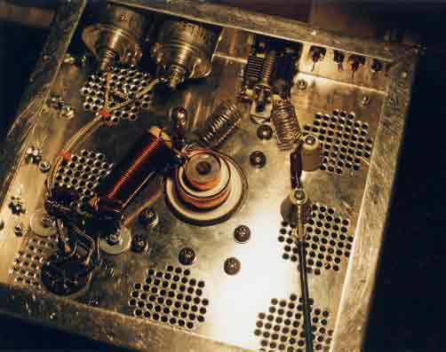

1. Bottom side inside the cathode compartment
|
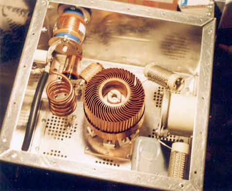
2. Top side, inside the anode compartment
|
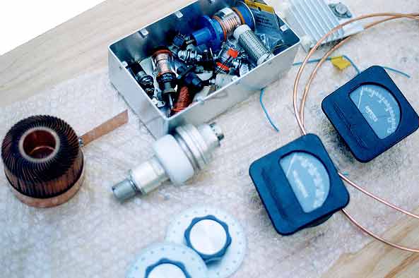
3. Major parts collection before construction began
|
|
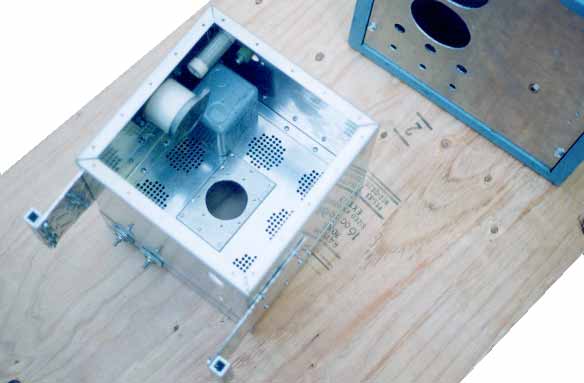
4. The main Boxes. The RF deck goes inside the cabinet
on upper right
|
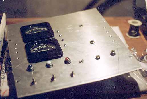
5. The front panel starting to take shape
|
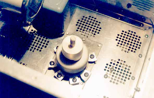
6. The GS35B with anode radiator removed. It is held
down with heavy duty clips made from angle aluminum.
|
AFTER CONSTRUCTION
(Click
on pictures for zoom)
 7. The front of the amplifier. The big meters are from
an old FM broadcast transmitter. The top meter measures 0-1.5A for plate
current and the bottom one measures 0-500mA for grid current. The top knob on
the right is for the loading capacitor, a 250 pf vacuum variable. The knob
beneath it is for the plate tune capacitor, a 3-30 pf vacuum variable. The
total dimensions of the RF deck are 11x11x11 inches (28x28x28 cm). I mounted a
flange for air input on the back to pipe air from a remote blower to keep the
noise down at the operating position.
7. The front of the amplifier. The big meters are from
an old FM broadcast transmitter. The top meter measures 0-1.5A for plate
current and the bottom one measures 0-500mA for grid current. The top knob on
the right is for the loading capacitor, a 250 pf vacuum variable. The knob
beneath it is for the plate tune capacitor, a 3-30 pf vacuum variable. The
total dimensions of the RF deck are 11x11x11 inches (28x28x28 cm). I mounted a
flange for air input on the back to pipe air from a remote blower to keep the
noise down at the operating position.
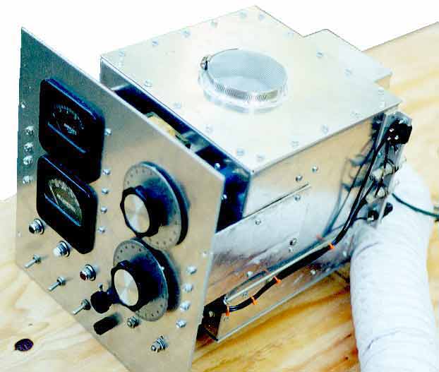 8. A view of the top. To vent the hot air from the
anode compartment, I am using a chimney made of sheet teflon (ptfe). A flange
of the same diameter as the anode was brazed onto the anode compartment lid in
order to attach the chimney to the lid. Some screening cloth was fitted over
the top of the flange and secured with a large hose clamp.
8. A view of the top. To vent the hot air from the
anode compartment, I am using a chimney made of sheet teflon (ptfe). A flange
of the same diameter as the anode was brazed onto the anode compartment lid in
order to attach the chimney to the lid. Some screening cloth was fitted over
the top of the flange and secured with a large hose clamp.
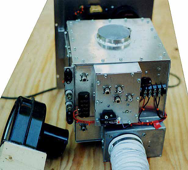 9. A view of the back. The air is fed into the cathode
compartment via a shielded box and a plastic flange fashioned from a 4-inch ABS
toilet flange. The flange was inexpensive and a good fit for 4-inch dryer hose
used to transport air to the amplifier. The flexible hose is going to be used
as a union between the amplifier and the ABS pipe going to an adjacent room
where the blower will be. The blower rating will be 150 cubic feet per minute.
9. A view of the back. The air is fed into the cathode
compartment via a shielded box and a plastic flange fashioned from a 4-inch ABS
toilet flange. The flange was inexpensive and a good fit for 4-inch dryer hose
used to transport air to the amplifier. The flexible hose is going to be used
as a union between the amplifier and the ABS pipe going to an adjacent room
where the blower will be. The blower rating will be 150 cubic feet per minute.
 I got the amplifier running, but went through a few trials and tribulations
first. Now that I have it going, it runs like a champ! It's unconditionally
stable. For those who are considering a similar amplifier, I recommend reading
through the QRO pages on this site, particularly the article written by Bill,
K8CU. Another wealth of information can be found on Rich,
AG6K's web page.
I got the amplifier running, but went through a few trials and tribulations
first. Now that I have it going, it runs like a champ! It's unconditionally
stable. For those who are considering a similar amplifier, I recommend reading
through the QRO pages on this site, particularly the article written by Bill,
K8CU. Another wealth of information can be found on Rich,
AG6K's web page.
|
|