|
Click
on picture for zoom
.
|
|
|
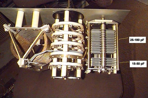
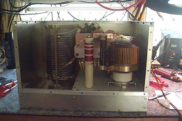
Rear view of output circuitry showing both inductors, tuning and loading capacitors, and
bandswitch. The 28uH coil is a commercial unit salvaged from used equipment. It was
mfr'd by Multronics (USA) part number 260-73007-3. The tuning capacitor is a dual section,
5KV, mfr Lapointe (Rockville CONN), part number 105-31. The 2000 pF, 1KV loading capacitor
is mfr'd by Lapointe (Rockville CONN), part number 104-47. The bandswitch is 5 pole 11 throw,
with 30 degree indexing.
|
| |
|
|
Top view: The 2nd switch wafer selects one or both sections of the tuning capacitor for use
on a given band; the 1st & 4th wafers add padding capacitors for LF bands. The 3rd wafer
shorts out plate coil turns; the shorting common contact is at the 50 ohm end of the coil.
The 5th wafer is currently unused; may use it to select input matching circuits.
|
| |
|
|
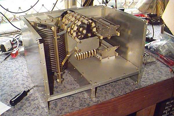
Rear view of the amplifier with the GS-35b in place. A 60mm hole was cut in the chassis and
carefully filed until the grid was a press fit into the hole. The chassis is 1.6mm aluminium.
The top of the grid ring is clamped to the chassis by 1.6mm aluminium formed into an "L" shaped
brackets and drilled along the top surface. These are then bolted through the chassis; the
nuts on the bolts are tightened from the filament compartment.
|
| |
|

|
The filament wiring: The bifilar-wound toroidal filament RF choke is 14 turns #18 AWG or larger
on an X" toroid of Philips 4B6 material, mounted between two fiberglass wafers, bolted to
chassis. The choke input is through 10 nF (.001 microFarad), 1KV feedthroughs. The choke
output is to a pair of standoffs; a 10 nF, 1KV mica capacitor between them shorts the filament
for RF. The GS-35b connections are brass straps in a clamping arrangement.
|
| |
|
|
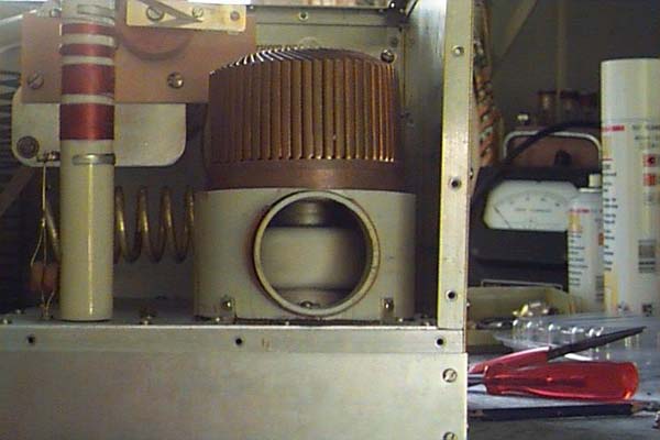
View of the air flow "chimney" of the GS-35b. This tube requires at least 90 cubic feet per
minute (~150 cubic meters per hour) of air flow to keep tube temperatures within spec's. The
"chimney" is a 100mm PVC conduit junction. It is bolted to the chassis by 4 "L" brackets. On
the bottom of the conduit is a gasket of cork material to get a good air seal. The air entry
port of the system accepts a 50mm PVC conduit fed by a blower.
|
| |
|
|
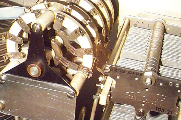
A close-up of the hefty bandswitch for this full legal limit HF amplifier. It was removed
from an old Canadian-built amplifier, but believe it similar to switches used by SRS and
others. Switches are sold by Surplus Sales of Nebraska
|
| |
|

|
Bottom view of the chassis during early stages of construction. The coil is supported by
fibre bars clamped together at the ends with metal brackets, each with two ceramic insulators
attached to mount the assembly to the chassis.
|
| |
|
|
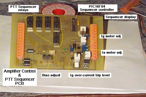
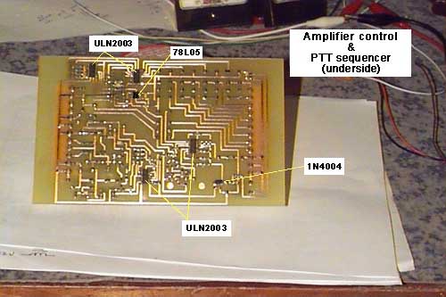
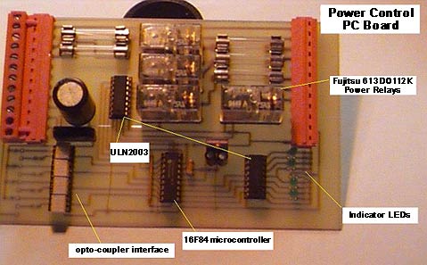
The PA power control board: A thorough description is found with the full sized picture.
SCHEMATIC
|
| |