|
23CM GS-15b POWER TESTS |
|
Initial testing was done with quickly built coaxial lines, improvising, using a lot of hose clamps just to see if 1296 MHz operation is possible. This is above the rated frequency listed. Results were good with 150W output at 40+% efficiency and very low drift using air-cooling only. Also encouraging was the low currents drawn by both grids of this tetrode at 23cm. |
|
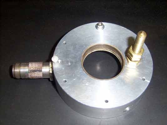
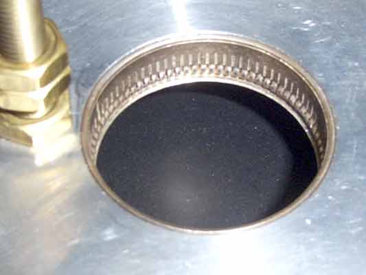
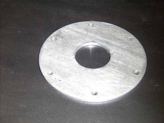
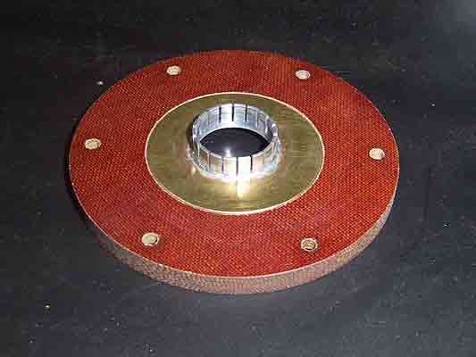
A cavity was designed and built for further testing. The output capacitance of typically 1.9 pF is less than that of a 7289 (2C39). So a circular cavity was made with dimensions a little larger than the N6CA design. The driven cathode input is a 3/4 wavelength coaxial line with an internal sleeve bypass for grid # 1 and the screen grid is directly grounded. With the anode projecting out from the cavity, air-cooling is easy and water-cooling can be added later when the 200 W anode dissipation is exceeded. Air-cooled results are 250W output at 50+% efficiency with 10 to 15 W drive from a M-57762 power module. Pictures of the prototype benchmark test PA are presented below: |
|
Click on picture for zoom |


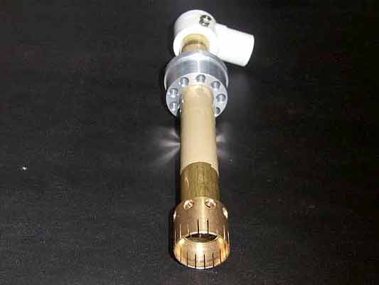
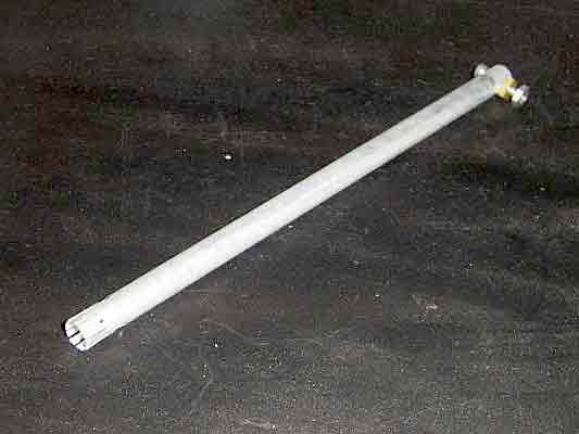
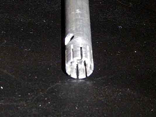
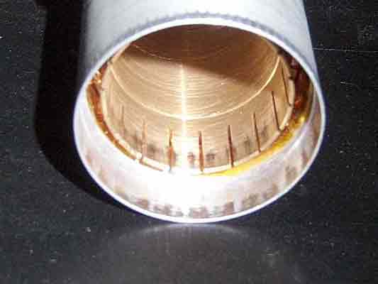
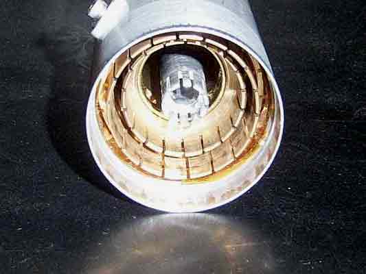

| PA designed & built by N8OU |
 22-Cath-cooling-heater-terminal |
 23-Completed-Amp-Side-view |
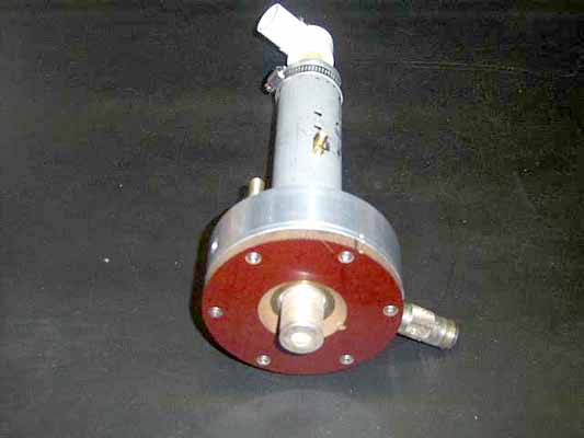 24-Completed-Amp-Top-view |
Photos by KD5FZX (SM6IKY) |
|
Maximum output achieved with 15w drive was 300W. The anode voltage was 2000 with 600W input
power. Air cooling was used and several ratings were being exceeded. This tetrode amplifier
is more stable and lower in drift than any triode tested here at 23cm. Finding the upper power
limit did destroy several tubes in the learning process. The anode radiator is small for the
200W rating and runs very hot. This is a planer tetrode with a cathode diameter of 11mm and
can support currents of 400+ma in amateur service. The grids are flat sheet, with window
openings that are inline for low intercept, resulting in very low grid currents. Anode
dissipation is clearly the first limiting factor.
|
|
There is a hole in the end of the anode radiator that can be tapped 3/8-24 fine thread or 10mm
to screw on an extension heat sink. For extreme testing, a 2 piece clamp on water cooled heat
exchanger was used. Failed tube examination revealed some limitations of operation. With 15w
and higher drive power, large detuning or loading changes can result in a permanent grid #1
distortion, as normal input transfer power becomes damaging heat. Screen grid voltage over
390 causes an arc-over at higher power tests and must be shunt regulated (zener stack), as
negative current becomes high during tuning and load range adjustments. The 280w output test
was run for long periods and general anode cavity heating was observed, showing a need to add
some air flow. At 380w output, small rapid tuning drift could be seen, indicating internal
tube changes and key down times were under 10 seconds. The higher power tests had more drift
and needed the tuning favoring lower screen current. The 500w output tests were unstable and
were run just long enough to get readings.
|
|
Class B efficiency (near cutoff) was highest at 55% at 250w levels; operation at higher power must be Class AB to lower drive and tube damage with some loss of efficiency. The 15w M-57762 power module is common to many setups and 250 to 300 watts output is easy to obtain. To find the upper anode voltage limit would require a different power supply, as the one used was capable of only 2600VDC, no load. |
23cm GS-15B Empirical Data
(Low Drive Data in second table)
| Va | 1500 | 1600 | 1700 | 1650 | 1800 | 2200 | 2200 | 2200 | 2200 | 2200 | 2300+ |
| Vg2 | 280 | 310 | 340 | 320 | 370 | 410 | 390 | 390 | 390 | 390 | 390 |
| Ig2 (mA) | 0/-1 | 0/-1 | 0/-1 | 0/-1 | 0/-1 | 0/-2 | -1/-2 | -1/-3 | -2/-3 | -2/-4 | -2/-5 |
| Vg1 | -36 | -36 | -36 | -45 | -45 | -45 | -45 | -45 | -45 | -45 | -45 |
| Ig1 (mA) | 0 | 5 | 4 | 1 | 4 | 2 | 4 | 7 | 10 | 15 | 10 |
| Ia (mA) | 190 | 250 | 280 | 250 | 280 | 300 | 330 | 380 | 410 | 430 | 440 |
| Iq (mA) (idle) | 10 | 25 | 40 | 0 | 20 | 55 | 40 | 40 | 40 | 40 | 40 |
| W in | 285 | 400 | 480 | 410 | 505 | 660 | 730 | 840 | 900 | 950 | 1010 |
| W out | 140 | 210 | 250 | 230 | 280 | 320 | 380 | 425 | 455 | 480 | 500 |
| Eff. (%) | 50 | 52 | 52 | 55 | 55 | 48 | 52 | 50 | 50 | 50 | 49 |
| Drive (W) | 10 | 13 | 13 | 13 | 15 | 15 | 20 | 25 | 30 | 35 | 35+ |
Low Drive 23cm GS-15B Empirical Data
Ig1 & Ig2 were all between 0 and -0.5 mA
| Va | 1750 | 2000 | 2150 | 2250 | 2400 | 2600 |
| Vg2 | 400 | 380 | 420 | 400 | 410 | 430 |
| Vg1 | -36 | -36 | -45 | -36 | -36 | -45 |
| Ia (mA) | 200 | 175 | 210 | 190 | 220 | 225 |
| Iq (mA) | 90 | 75 | 60 | 100 | 110 | 70 |
| W in | 350 | 350 | 450 | 430 | 530 | 585 |
| W out | 175 | 120 | 210 | 140 | 175 | 245 |
| Eff. (%) | 40 | 34 | 46 | 32 | 33 | 42 |
| Drive (W) | 4 | 3 | 6.5 | 3 | 4 | 6.5 |
| Anode Dissipation (W) | 210 | 230 | 240 | 290 | 355 | 330 |
| Operation | Good | Good | Good | Poor | Poor | Poor |