by
KD5HIO
Click on callsign for KD5HIO e-mail
|
Chassis Details
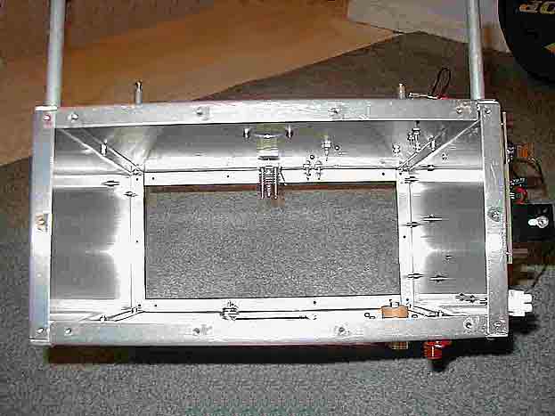
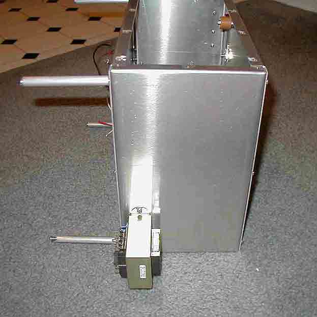
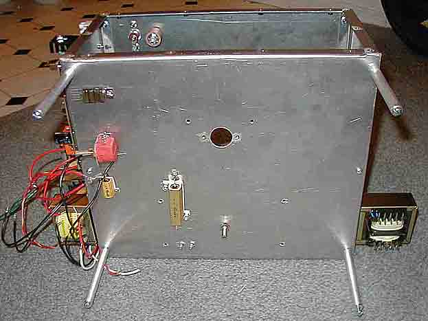
The pictures below show the chassis with basic installation of parts already begun.
|
|
|
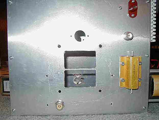
 Front view |
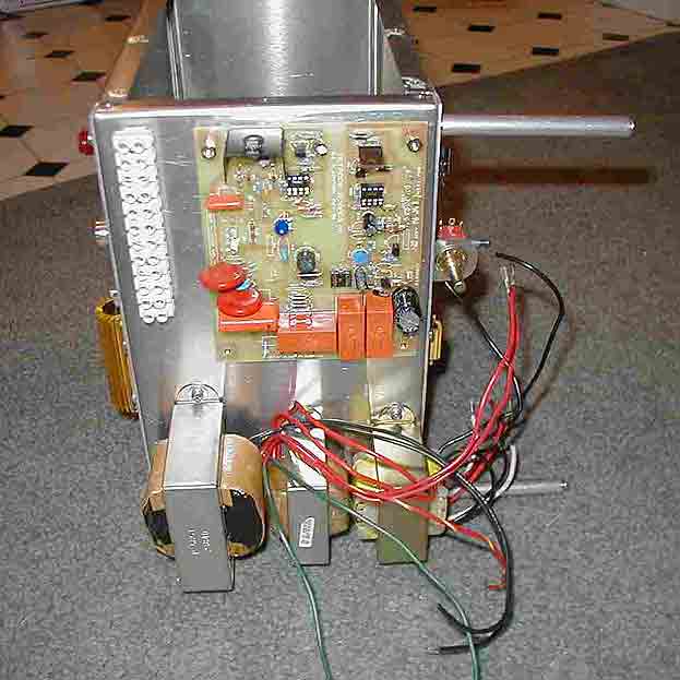
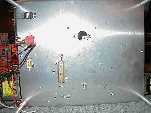 Front, close-up |
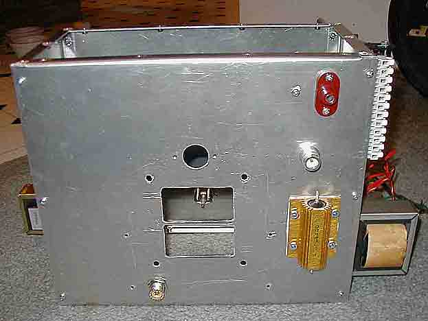
 Front, completed, from bottom |
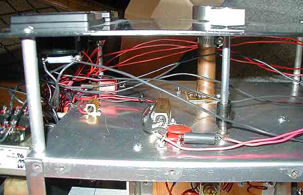
The picture at right shows the area between the front panel of the amp and the faceplate, viewed from below. The shaft for the input tune control is near the bottom, the mechanical apparatus for the plate tune is above this. To the left is the resistor that bleeds 10 mA of G2 current to the cathode. Further right is R14, and RV102 (not actually used in the final version). Above RV102 is Q2 (barely visible). Also visible are the feedthrough caps C10 & C11 for the filament voltage to the tube, and the varsistors that protect the screen bypass capacitors and tetrode boards in case of HV flashover to G2. Lastly, a low-value resistor is used to drop the filament voltage generated by the filament transformer to no more than 6.3 VAC, measured right at the tube. |
go to the top